Mastering SiC Machining for Production Excellence

Share
Mastering SiC Machining for Production Excellence
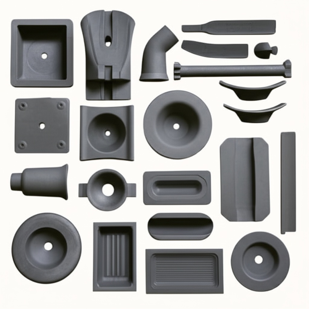
Silicon Carbide (SiC) stands as a cornerstone material in today’s most demanding industrial applications. Its exceptional hardness, high thermal conductivity, superior wear resistance, and chemical inertness make it indispensable across sectors like semiconductors, automotive, aerospace, power electronics, and renewable energy. However, these very properties present significant challenges in fabrication. Mastering SiC machining is not just a technical feat; it’s a prerequisite for achieving production excellence and unlocking the full potential of this advanced ceramic. This blog post delves into the intricacies of SiC machining, exploring techniques, challenges, and pathways to optimized production for engineers, procurement managers, and technical buyers.
1. Introduction: The Unyielding Challenge and Promise of Machining Silicon Carbide
Silicon Carbide (SiC) is a synthetic crystalline compound of silicon and carbon. Its remarkable physical and chemical properties make it a sought-after material for components operating in extreme conditions. From furnace components enduring scorching temperatures to precision parts in semiconductor manufacturing equipment, SiC delivers performance where other materials falter. However, the inherent characteristics that make SiC so valuable—primarily its extreme hardness (second only to diamond) and brittleness—render it notoriously difficult to machine using conventional methods. The machining of SiC is a specialized field requiring deep material science knowledge, advanced equipment, and meticulously developed processes. The promise lies in transforming this challenging material into highly reliable, precision components that drive innovation and efficiency in high-performance industries. Successfully machining SiC translates to enhanced product lifespans, improved operational efficiencies, and the ability to push technological boundaries.
Keywords: Silicon Carbide machining, advanced ceramics, high-performance materials, industrial SiC components, SiC fabrication.

2. Why Silicon Carbide Demands Specialized Machining Expertise
The unique attributes of Silicon Carbide necessitate a departure from standard machining practices. Understanding these properties is key to appreciating the need for specialized expertise:
- Extreme Hardness: SiC typically registers 9-9.5 on the Mohs scale (diamond is 10) and over 2500 Knoop. This means conventional cutting tools wear out exceptionally fast or are simply ineffective, leading to high tooling costs and low productivity if not managed correctly. Diamond, being harder than SiC, is the primary abrasive used.
- Brittleness: Despite its hardness, SiC is a brittle material. This means it is prone to chipping, micro-cracking, and catastrophic fracture under inappropriate machining forces or thermal shock. Machining processes must be carefully controlled to minimize stress concentrations.
- High Wear Resistance: While a benefit in end-use applications, SiC’s wear resistance also applies to its interaction with machining tools, leading to rapid tool degradation.
- Chemical Inertness: SiC’s resistance to chemical attack at high temperatures is advantageous for many applications but can limit options for chemical-assisted machining processes.
- Thermal Properties: While SiC has excellent thermal conductivity, localized heating during machining can still induce thermal stresses, potentially leading to cracks if not managed with proper cooling and machining parameters.
These factors mean that machining SiC is not merely about material removal; it’s about doing so while preserving the material’s integrity, achieving tight dimensional tolerances, and producing desired surface finishes. This requires specialized equipment, optimized process parameters, and a workforce skilled in the nuances of hard material machining. Procurement managers and technical buyers must recognize that low-cost machining attempts by inexperienced vendors often result in failed parts, project delays, and ultimately higher overall costs.
Keywords: SiC material properties, hard material machining, brittle material machining, diamond tooling, SiC machinability.
3. A Spectrum of SiC Machining Techniques: From Traditional to Advanced
A variety of machining techniques have been developed or adapted to shape Silicon Carbide components. The choice of method depends on factors such as the SiC grade (e.g., sintered SiC (SSiC), reaction-bonded SiC (RBSC), nitride-bonded SiC (NBSC), CVD SiC), part complexity, required tolerances, surface finish, and production volume.
| Technique | Description | Typical Applications | Advantages | Limitations |
|---|---|---|---|---|
| Diamond Grinding | Utilizes diamond abrasive wheels to remove material. Most common method for SiC. | Shaping, sizing, achieving flat/cylindrical surfaces. | Good material removal rates, capable of high precision. | Can induce sub-surface damage if not optimized; tool wear. |
| Lapping & Polishing | Uses fine diamond slurries on a lapping plate or polishing pad to achieve very smooth and flat surfaces. | Optical components, semiconductor wafers, seal faces. | Excellent surface finish (Ra < 1 nm possible), high flatness. | Slow material removal; primarily for finishing. |
| Electrical Discharge Machining (EDM) | Removes material through a series of rapidly recurring electrical discharges between an electrode and the workpiece, submerged in a dielectric fluid. Applicable to conductive SiC grades or SiC composites. | Complex shapes, small holes, intricate features. | Can machine complex geometries; no direct tool-workpiece contact. | Slower than grinding; only for conductive SiC; potential for thermal damage. |
| Laser Beam Machining (LBM) | Uses a focused high-energy laser beam to melt, vaporize, or ablate material. | Drilling small holes, scribing, cutting thin sections, micro-machining. | Non-contact process; high speed for specific tasks; can create fine features. | Heat-affected zone (HAZ); potential for micro-cracks; material redeposition. |
| Ultrasonic Machining (USM) | A tool vibrating at ultrasonic frequencies propels an abrasive slurry against the workpiece surface, causing material erosion. | Machining hard and brittle materials, drilling holes, creating cavities. | Good for non-conductive SiC; low thermal stress. | Lower material removal rate; tool wear. |
| Abrasive Waterjet Cutting (AWJC) | A high-pressure water jet mixed with abrasive particles erodes the material. | Cutting thick sections, rough shaping. | No HAZ; can cut complex contours. | Lower accuracy and surface finish compared to grinding; taper on cuts. |
Understanding this spectrum allows engineers and designers to select the most appropriate technique or combination of techniques for their specific SiC component requirements.
Keywords: SiC grinding, SiC lapping, EDM SiC, Laser machining SiC, Ultrasonic machining SiC, Abrasive Waterjet SiC.
4. Precision Grinding of Silicon Carbide: The Workhorse of SiC Machining
Diamond grinding is the most widely employed method for machining Silicon Carbide due to its effectiveness in removing hard material and achieving precise dimensions. Success in SiC grinding hinges on several critical factors:
- Diamond Abrasive Selection:
- Type: Synthetic diamonds are commonly used. Metal-bonded diamond wheels are preferred for their durability and form-holding capabilities in SiC grinding. Resin-bond wheels might be used for finer finishes but have higher wear rates. Vitrified bonds offer good material removal and form holding.
- Grit Size: Coarser grits (e.g., 60-100 mesh) are used for roughing and high stock removal, while finer grits (e.g., 400-800 mesh and finer) are used for finishing operations to achieve better surface quality.
- Concentration: Diamond concentration in the wheel affects cutting efficiency and wheel life. Higher concentrations are often used for harder SiC grades.
- Grinding Machine Characteristics: High rigidity, minimal vibration, and precise control over speeds and feeds are essential. CNC grinding machines offer the best control and repeatability.
- Operating Parameters:
- Wheel Speed: Optimal speeds (typically 20-35 m/s) depend on the wheel type, SiC grade, and operation.
- Feed Rate: Must be carefully controlled to avoid excessive force, which can cause chipping or cracking. Slower feed rates are typical for SiC.
- Depth of Cut: Small depths of cut are generally used, especially during finishing passes, to minimize sub-surface damage.
- Coolant Application: Effective cooling is crucial to dissipate heat generated during grinding, prevent thermal damage to the workpiece, and flush away swarf. Synthetic coolants or deionized water are often used.
Different SiC grades, such as Sintered Silicon Carbide (SSiC), Reaction-Bonded Silicon Carbide (RBSC), and Chemical Vapor Deposited (CVD) SiC, exhibit variations in hardness, toughness, and internal stresses. These variations necessitate adjustments in grinding parameters. For example, RBSC, containing free silicon, might be slightly easier to machine than fully dense SSiC.
Keywords: Diamond grinding SiC, SiC grinding wheels, CNC SiC grinding, Sintered SiC machining, Reaction Bonded SiC machining, grinding parameters.
5. Achieving Superior Finishes: Lapping and Polishing SiC Components
For applications demanding exceptionally smooth surfaces, high flatness, and minimal sub-surface damage—such as in semiconductor processing equipment, optical mirrors, and high-performance seal faces—lapping and polishing are indispensable post-grinding steps for Silicon Carbide.
- Lapping: This process involves using a loose abrasive slurry (typically diamond particles suspended in a liquid carrier) between the SiC workpiece and a lapping plate (often made of cast iron or a specialized composite). The workpiece moves in a random or controlled path across the plate.
- Objective: To improve flatness, parallelism, and surface finish (typically in the range of Ra 0.05 to 0.2 µm), and to remove sub-surface damage induced by prior grinding operations.
- Abrasives: Diamond slurries with particle sizes ranging from 3 µm to 30 µm are common, depending on the desired removal rate and initial surface condition.
- Polishing: Polishing follows lapping to achieve even finer surface finishes, often to optical quality (Ra < 1 nm). This process uses finer diamond abrasives (typically < 1 µm, down to nanometer scale) on a polishing pad, which can be made of various materials like polyurethane, felt, or specialized composites.
- Objective: To achieve a mirror-like finish, minimize light scattering, and further reduce any remaining micro-scratches or sub-surface damage.
- Techniques: Mechanical polishing is common. Chemo-Mechanical Polishing (CMP) can also be employed for SiC, where chemical action assists the mechanical removal, leading to superior surface integrity.
Key considerations for successful SiC lapping and polishing include:
- Abrasive Size and Type: Progressively finer diamond particles are used as the process moves from lapping to final polishing.
- Lapping Plate/Polishing Pad Material: The choice impacts material removal rate and achievable finish.
- Slurry Composition and Flow: Proper distribution and lubrication are critical.
- Pressure and Speed: These parameters must be carefully controlled to avoid introducing new defects.
- Cleanliness: Maintaining a clean environment is crucial, as even small contaminants can cause scratches.
Achieving nanometer-level surface finishes and angstrom-level roughness on SiC components requires significant expertise and specialized equipment, making it a hallmark of advanced ceramic machining providers.
Keywords: SiC lapping, SiC polishing, surface finish SiC, flatness SiC, optical SiC components, chemo-mechanical polishing (CMP) SiC.

6. Navigating Complexity: Advanced Machining for Intricate SiC Designs (EDM, Laser, USM)
While grinding, lapping, and polishing form the backbone of SiC machining, certain applications demand intricate features, complex geometries, or micro-scale details that are challenging or impossible to achieve with these traditional methods. Advanced machining processes offer solutions for these complexities:
- Electrical Discharge Machining (EDM):
- Principle: EDM uses thermoelectric erosion to remove material. It requires the workpiece to be electrically conductive. While pure SiC is a semiconductor, its conductivity can be insufficient for efficient EDM. However, certain grades of SiC, like some types of RBSC with significant free silicon, or SiC composites with conductive phases, can be effectively machined using EDM. SSiC can also be EDMed, albeit at slower rates.
- Applications: Creating complex 3D cavities, sharp internal corners, small deep holes, and intricate patterns. Wire EDM can be used for cutting complex profiles.
- Advantages: No mechanical force, so good for delicate parts. Ability to machine very hard materials.
- Considerations: Relatively slow material removal rates. Potential for a recast layer or heat-affected zone on the machined surface, which may require post-processing.
- Laser Beam Machining (LBM):
- Principle: A high-intensity focused laser beam melts and vaporizes or ablates the SiC material. Different laser types (e.g., Nd:YAG, excimer, femtosecond lasers) offer varying characteristics suitable for different tasks.
- Applications: Drilling micro-holes (e.g., for fuel injectors, cooling channels), scribing wafers, cutting thin SiC substrates, creating surface textures, and micro-patterning.
- Advantages: Non-contact process, high processing speed for certain tasks, ability to create very fine features. Femtosecond lasers minimize thermal damage.
- Considerations: Heat-affected zone (HAZ) and micro-cracking can be issues with some laser types if not carefully controlled. Material redeposition can occur.
- Ultrasonic Machining (USM) / Ultrasonic Vibration Assisted Grinding (UVAG):
- Principle (USM): A tool, shaped to the desired feature, vibrates at ultrasonic frequencies (typically >20 kHz) and drives abrasive particles (in a slurry) against the workpiece surface, causing micro-chipping and erosion.
- Principle (UVAG): Superimposes ultrasonic vibration onto a conventional grinding wheel or tool. This reduces cutting forces, improves surface finish, and can enhance material removal rates.
- Applications: Drilling round or shaped holes, milling cavities in hard and brittle materials like SiC. UVAG enhances grinding performance.
- Advantages: Effective for both conductive and non-conductive SiC. Low thermal stress. Can produce good surface finishes.
- Considerations: Material removal rates can be lower than conventional grinding for bulk removal. Tool wear is a factor.
The selection of an advanced machining process depends heavily on the specific geometric requirements, material properties of the SiC grade, and cost-benefit analysis for the application. These techniques often complement traditional methods, providing solutions for features that would otherwise be unmachinable.
Keywords: EDM silicon carbide, laser machining silicon carbide, ultrasonic machining SiC, micro-machining SiC, complex SiC parts, advanced SiC fabrication.
7. Tooling for Success: Selecting and Managing Tools for SiC Machining
Given Silicon Carbide’s extreme hardness, the selection and management of cutting tools are paramount for successful and cost-effective machining. Diamond is the undisputed champion material for tooling in SiC applications.
- Diamond Tooling:
- Types:
- Metal Bond Diamond Tools: Diamond particles are sintered in a metallic matrix (e.g., bronze, steel, cobalt alloys). These are robust and wear-resistant, suitable for grinding wheels and core drills. They offer good form holding.
- Resin Bond Diamond Tools: Diamond particles are held in a resinoid matrix. These tools provide a softer cutting action and can produce better surface finishes but wear faster than metal bonds. Often used for fine grinding and polishing.
- Vitrified Bond Diamond Tools: Diamond particles are bonded in a glass-like matrix. These offer a good balance of material removal rate, wear resistance, and form-holding ability. They can be dressed to maintain sharpness.
- Electroplated Diamond Tools: A single layer of diamond particles is bonded to a tool substrate by nickel plating. Good for complex forms and free-cutting action but have limited life.
- Polycrystalline Diamond (PCD) Tools: PCD consists of sintered diamond particles, creating a continuous diamond cutting edge. PCD tools are extremely wear-resistant and are used for turning, milling, and drilling SiC, especially RBSC or SiC with lower hardness. They offer longer tool life in specific applications compared to abrasive tools.
- Key Tool Parameters: Diamond grit size, concentration, bond type, and tool geometry (e.g., rake angle, clearance angle for PCD tools) must be carefully selected based on the SiC grade, machining operation (roughing, finishing), and desired outcome.
- Types:
- Tool Wear Mechanisms in SiC Machining:
- Abrasive Wear: The primary wear mechanism due to the hardness of SiC particles.
- Attritious Wear: Flattening of the diamond grit cutting edges.
- Bond Erosion: The bond material holding the diamond grits wears away, leading to grit pull-out.
- Micro-fracturing: Diamond grits can chip or fracture under high cutting forces.
- Strategies for Extending Tool Life and Managing Costs:
- Optimal Machining Parameters: Using correct speeds, feeds, and depths of cut to minimize stress on the tool.
- Effective Cooling and Lubrication: Reduces thermal load and helps flush away abrasive SiC particles.
- Tool Dressing and Truing (for grinding wheels): Regularly exposing fresh diamond grits and maintaining the wheel’s geometric accuracy.
- High-Quality Tooling: Investing in superior quality diamond tools from reputable suppliers often yields better overall cost-effectiveness despite higher initial cost.
- Process Monitoring: Using acoustic emission sensors or power monitoring to detect early signs of tool wear or process instability.
Tooling represents a significant cost component in SiC machining. Therefore, a comprehensive tooling strategy, encompassing careful selection, optimized usage, and proactive management, is crucial for achieving production excellence and competitive pricing.
Keywords: Diamond tools for SiC, PCD tooling SiC, SiC grinding wheels, tool wear SiC, machining tooling, cost of SiC machining.
8. Overcoming Key Challenges in Silicon Carbide Machining and Ensuring Component Integrity
Machining Silicon Carbide is fraught with challenges that can compromise component integrity if not properly addressed. Understanding these challenges and implementing effective mitigation strategies is vital for producing reliable SiC parts.
- Brittleness and Fracture:
- Challenge: SiC’s low fracture toughness makes it susceptible to chipping, edge fracture, and catastrophic cracking under excessive mechanical or thermal stress.
- Mitigation:
- Employing low cutting forces (small depths of cut, controlled feed rates).
- Using high-stiffness machine tools to minimize vibrations.
- Optimizing tool geometry (e.g., sharp cutting edges, appropriate chamfers on tools).
- Gradual heating and cooling if thermal processes are involved.
- Designing parts to minimize stress concentrations (e.g., rounded corners instead of sharp internal angles where possible).
- Sub-Surface Damage (SSD):
- Challenge: Grinding and other machining processes can introduce a layer of micro-cracks, residual stresses, and amorphized material beneath the machined surface. SSD can significantly degrade the mechanical strength and performance of the SiC component.
- Mitigation:
- Using a multi-stage grinding process, starting with coarse grits for material removal and progressing to finer grits for finishing to reduce SSD.
- Employing gentle machining parameters (low feed, low depth of cut) in final passes.
- Lapping and polishing to remove the damaged layer.
- Annealing post-machining can sometimes relieve stresses and heal minor cracks, though its effectiveness varies with SiC type and damage severity.
- Surface Integrity (Roughness and Waviness):
- Challenge: Achieving the desired surface finish (Ra, Rz) and form accuracy (waviness, flatness) can be difficult due to tool wear and the material’s hardness.
- Mitigation:
- Proper selection of abrasive grit size and tool type.
- Optimized lapping and polishing processes for ultra-smooth surfaces.
- Using well-maintained, high-precision machinery.
- Regular dressing and truing of grinding wheels.
- Tool Wear and Machining Costs:
- Challenge: Rapid tool wear leads to increased tooling costs, machine downtime for tool changes, and potential inconsistencies in part quality.
- Mitigation:
- Using high-quality diamond tools optimized for SiC.
- Implementing optimal machining parameters and effective cooling.
- Exploring advanced tooling like PCD or specialized bond systems.
- Process monitoring to predict and manage tool life.
- Dimensional and Geometric Accuracy:
- Challenge: Holding tight tolerances on dimensions, profiles, and geometric features (e.g., perpendicularity, parallelism) is demanding due to the material’s properties and tool wear.
- Mitigation:
- Utilizing CNC machines with high accuracy and repeatability.
- Implementing in-process measurement and feedback control where possible.
- Careful planning of the machining sequence.
- Performing final machining operations under tightly controlled conditions.
Addressing these challenges requires a holistic approach that combines material science understanding, process engineering, metrology, and experienced personnel. This ensures that the machined SiC components not only meet dimensional specifications but also possess the required mechanical integrity for their intended high-performance applications.
Keywords: SiC machining challenges, sub-surface damage SiC, SiC component integrity, SiC fracture, dimensional accuracy SiC, reducing SiC machining costs.
9. Quality Assurance and Metrology for Machined SiC Components
Given the critical applications of Silicon Carbide components and the inherent challenges in their machining, a robust quality assurance (QA) and metrology framework is essential. Ensuring that machined SiC parts meet stringent specifications for dimensions, surface finish, and integrity is paramount.
Key aspects of QA and metrology for machined SiC include:
- Dimensional Inspection:
- Tools: Coordinate Measuring Machines (CMMs) for complex 3D geometries, optical comparators, micrometers, calipers, height gauges (often with diamond or carbide-tipped anvils for wear resistance).
- Considerations: Tolerances for SiC parts can be extremely tight (microns or sub-microns). Calibration of measurement equipment is critical.
- Surface Finish Measurement:
- Tools: Stylus profilometers (e.g., Talysurf) to measure surface roughness parameters like Ra (average roughness), Rz (average maximum height), Rq (root mean square roughness). Atomic Force Microscopy (AFM) for nanometer-scale roughness on super-polished surfaces. Non-contact optical profilometers (e.g., white light interferometry).
- Considerations: The type of surface finish measurement tool depends on the required resolution and the nature of the surface (e.g., flat, curved, micro-features).
- Form and Geometric Tolerance Verification:
- Parameters: Flatness, parallelism, perpendicularity, roundness, cylindricity, concentricity.
- Tools: CMMs, specialized form testers (e.g., roundness testers), interferometers for flatness assessment of optical surfaces.
- Sub-Surface Damage (SSD) Assessment:
- Techniques: While direct measurement is complex, indirect methods and destructive testing on sample parts can be used. These include:
- Cross-sectional microscopy: Polishing a cross-section of the machined part and examining it under a microscope (optical or SEM) to visualize micro-cracks.
- Strength testing (e.g., bend tests): Comparing the strength of machined samples to unmachined or ideally prepared samples. Significant strength reduction can indicate severe SSD.
- X-ray diffraction (XRD): Can detect phase transformations or residual stresses near the surface.
- Techniques: While direct measurement is complex, indirect methods and destructive testing on sample parts can be used. These include:
- Non-Destructive Testing (NDT):
- Dye Penetrant Inspection: Can reveal surface-breaking cracks.
- Ultrasonic Testing (High Frequency): Can detect internal flaws and sometimes sub-surface cracks, though challenging for fine SSD.
- Acoustic Microscopy: Useful for detecting near-surface defects.
- Process Control and Documentation:
- Implementing Statistical Process Control (SPC) to monitor and control machining parameters.
- Maintaining detailed records of machining processes, tool usage, and inspection results for traceability (crucial for aerospace, medical, and defense applications).
- Adherence to quality management systems like ISO 9001.
A comprehensive metrology strategy, integrated throughout the SiC machining workflow, from incoming material inspection to fina

CAS new materials
We, CAS new materials, have been introducing and implementing silicon carbide production technology since the 2015, assisting the local enterprises in achieving large-scale production and technological advancements in product processes. We have been a witness to the emergence and ongoing development of the local silicon carbide industry.
Customizable
Related Post
-
Custom SiC from Brazil Tailored to Your Specs
Custom SiC from Brazil Tailored to Your Specs In the relentless pursuit of peak performance across demanding industries, the limitations of traditional materials are becoming increasingly apparent. This drives a growing demand for advanced solutions that can withstand extreme conditions. Enter custom silicon carbide (SiC) – a revolutionary material offering unparalleled properties for critical applications….
-
Finding and Vetting SiC Suppliers in Russia
Finding and Vetting SiC Suppliers in Russia: A Comprehensive Guide for B2B Buyers In the evolving landscape of advanced materials, custom silicon carbide (SiC) products stand out for their exceptional properties, making them indispensable in high-performance industrial applications. As industries worldwide increasingly demand materials capable of withstanding extreme conditions, the search for reliable and technically…
-
Request a SiC Sample for Thorough Evaluation
Request a SiC Sample for Thorough Evaluation In the demanding world of advanced engineering, material selection is paramount. For applications requiring extreme performance in harsh environments, silicon carbide (SiC) stands out as a material of choice. Its exceptional properties, including superior hardness, chemical inertness, high thermal conductivity, and resistance to thermal shock, make it indispensable…